Going Fast, But Not Too Fast

Welcome back folks!
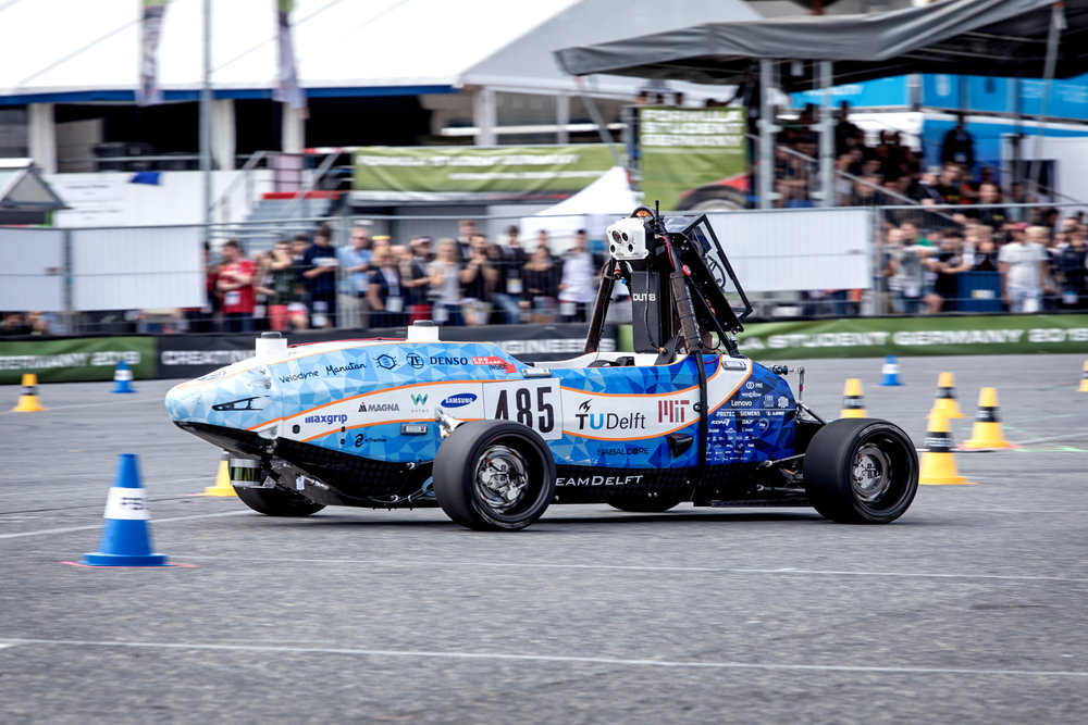
Leaves are turning, midterms are looming, and that means racecar is back in session. This year I’m excited to be work on MIT Motorsports FSAE Electric Racecar and to join Formula Student Driverless for their second year of collaboration with DUT Delft.
MIT Driverless is a really exciting project and I definitely plan to have updates on my vehicle modelling and controls work with them. For the moment though, I really want to document my power limiting work for Motorsports’s Electric team.
“What is power limiting,” you ask. “Don’t you want to use more power?” More power is more acceleration is faster lap times. A major goal of the team this year is to increase the rms power output from 15 kW to 25 kW. This requires a big technical leap to liquid battery cooling and is an exciting project for the battery team.
My job is to limit peak power. Our rules require us to draw no more 80 kW from the battery. At competition, the EE judge Dan Bocci actually installs a custom e-meter into the high voltage system to monitor compliance. In 2018, our racecar exceeded the limit for about 5 milliseconds off the line - enough to get us dequeued from the endurance event. It was real blow to the points total that year.
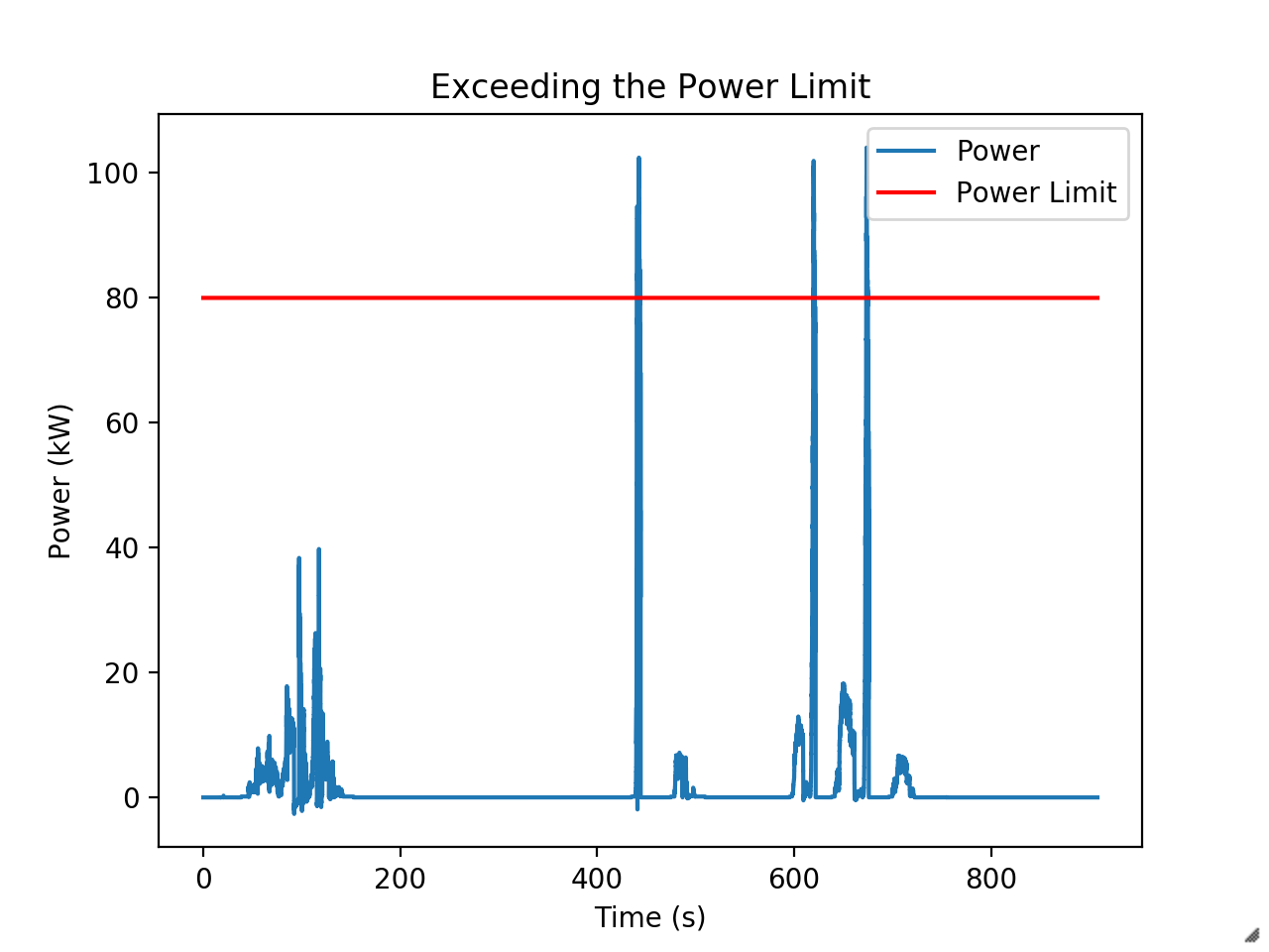
They’ve since changed the rules to just add a minute penalty, but limiting power is still required to have a competitive car. Our unlimited runs with the 2019 car have shown it will happily use more than 100 kW during acceleration if we let it. During competition we had to limit the driver’s maximum torque command by about a third to prevent exceeding the power limit. This was a big performance hit.
I’m responsible for implementing a better solution this year - one which only limits torque as necessary. The mechanical engineers in the audience might already have an idea for a strategy.
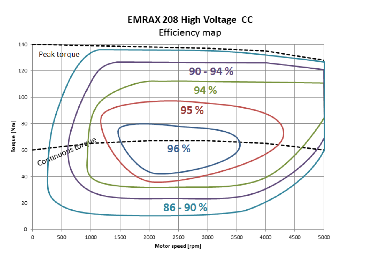
We can compute mechanical power, $ P = \tau \cdot \omega $, right? And we know motor speed from the Emrax motor’s resolver. So can’t we just limit torque, $ \tau = \frac{P}{\omega} $ such to never exceed 80 kW? There could be some inaccuracies from variation in motor efficiency over the torque-speed curve, but nothing a dynometer test and look-up table won’t solve.
The issue with this strategy is that we’ve not yet been able to successfully run a dynometer test and that it difficult to estimate the actual torque (and therefore efficiency) produced while driving.
We use a Rinehart motor controller. It is a very nice, very fancy machine which has been the bane of three power limiting leads. The inverter introduces many quirks that make predicting efficiency harder.
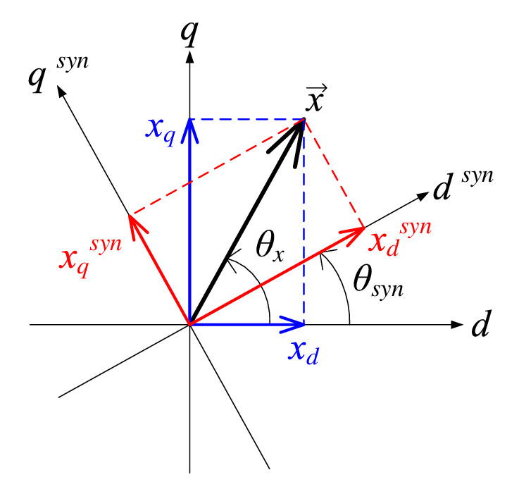
The Rinehart has its own internal control loop which converts a torque command to a $I_q$ target for field-oriented control. It then does PID control to track this target. This introduces the problem that the Rinehart usually isn’t producing exactly the torque you are commanding. If you try to later try to calculate efficiency using recorded electrical power, torque command, and resolver speed you’ll get incorrect inefficiencies. This includes efficiencies which are greater than $1$ or less than $0$ because frequently the vehicle won’t be producing as much torque as you are commanding. Part of this is just the traction limit of the car.
The Rinehart does give us a measurement called feedback torque which uses $I_q$ to produce a prediction of how much torque. However, this prediction is based on a linear relationship between $I_q$ and torque, when the relationship is non-linear. We could try to back out torque for ourselves using $I_q$ but it is hard to be confident of your results.
Field weakening introduces another level of complexity. Motor and generators are essentially the same device and so spinning a motor generates a back-emf proportional to speed. When this back-emf equals your bus voltage, you’ve reached the motor’s maximum speed and can’t command any more torque. The Emrax’s max speed with our battery voltage is less than the speeds we could see while driving and less than the thermal and mechanical speed limits of the motor. To command torque at higher speeds we use the Rinehart to produce $I_d$ current and produce torque over what would be the speed limit.
However, field weakening greatly reduces efficiency since $I_d$ current doesn’t produce torque. The onset of field weakening is depends on voltage which can sag and which changes as the battery is drained. This adds a third dimension to our lookup table.
If we want to run with different amounts of $I_d$ current (which we sometimes do) or control temperature you could need to add even more dimensions. The amount of data required and size of your lookup table quickly becomes impractical.
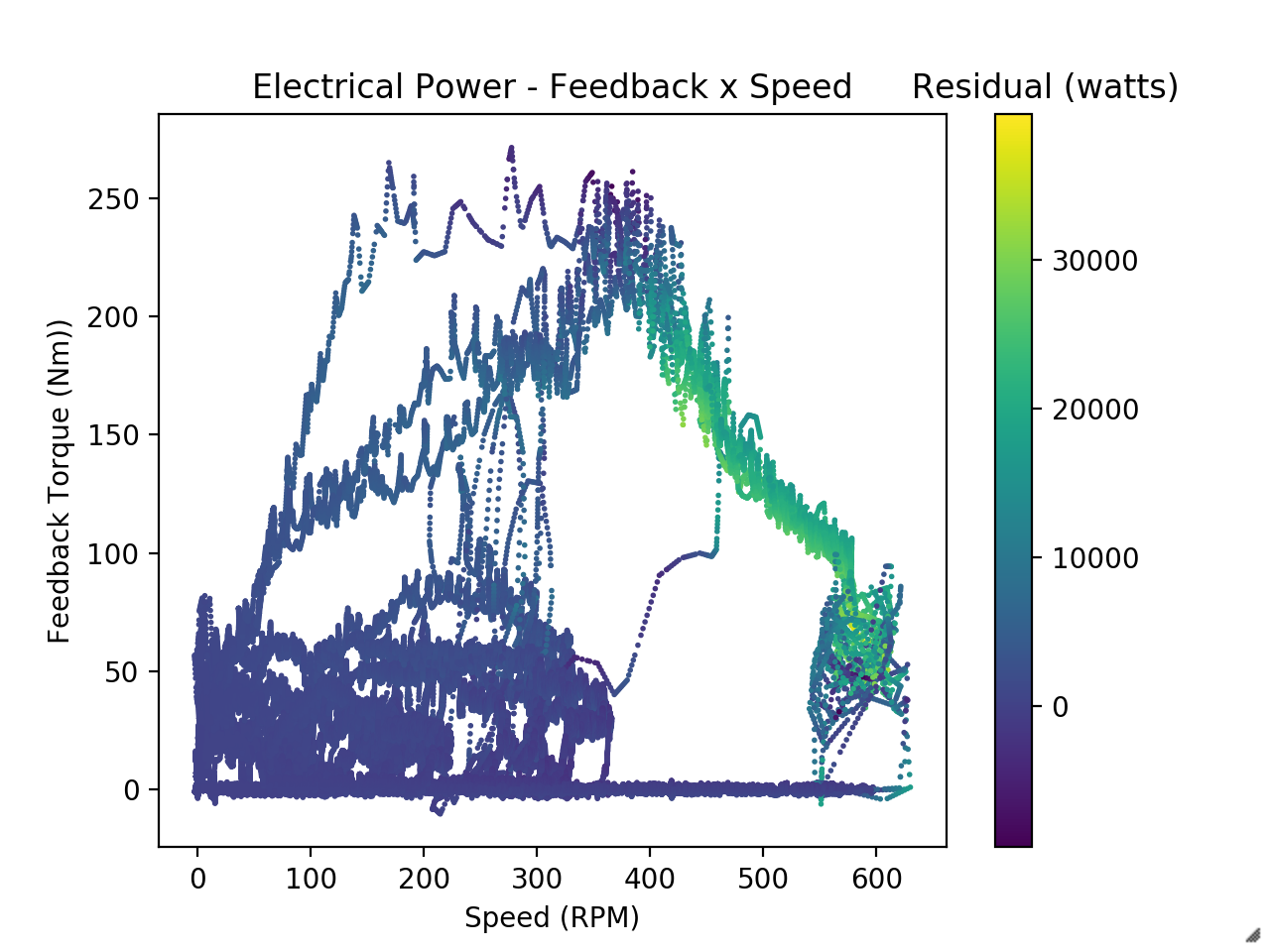
We’ve done a fair bit of analysis using just feedback torque and speed, but I think the way we’ll ultimately resolve this either by finally running a dynometer test or by using the magnetoelastic torque sensor we’re adding to model year 2020’s drivetrain to measure actual torque.
We use jupyter notebooks for data processing. Here’s the link to the live-hosted repository.